Summary for plant managers
If you're running robot fleets at the 5MW scale, you can't rely on basic hub-and-spoke setups. You need a self-healing wireless mesh topology. This architecture is critical for large Indian sites where module structures frequently block signals or gateways. A mesh setup ensures cleaning continues even when interference hits, maintaining reliable communication across expansive, dusty stretches where traditional star-topology Wi-Fi usually falls apart.
- Topology: Use self-healing mesh networks. For fleets exceeding 5MW, this eliminates single points of failure.
- Frequency Management: Stick to sub-GHz bands like LoRa for long-range commands, and use 2.4GHz for high-bandwidth telemetry and robot data.
- Interference Mitigation: Keep a 20dB signal separation from your plant SCADA to prevent control degradation.
- Latency Targets: End-to-end latency needs to stay below 200ms for real-time robot control.
- Operational Continuity: Decentralize your gateway architecture. It helps managers recover lost generation from soiling, especially during peak dust months in Rajasthan or Gujarat.
Moving to this framework stops O&M teams from constantly chasing manual connectivity fixes. Reliable networking is the backbone of scaling robotic cleaning systems and ensures your long-term O&M strategy actually hits its performance targets.
Why traditional Star topology fails in utility-scale solar O&M

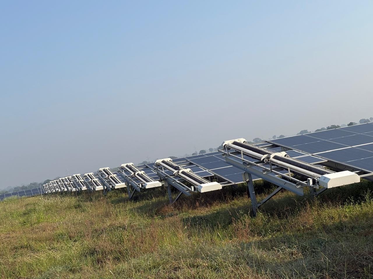
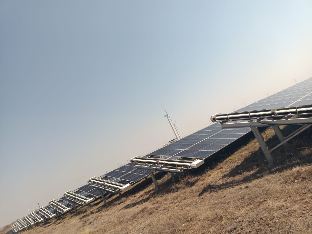
Once a plant climbs over 5MW, traditional Star topology starts causing downtime. In these models, every robot tries to connect to a single central gateway. But Indian solar sites aren't flat, open fields; varied row lengths and shadows often kill your line-of-sight. As robots move out, the signal drops, leading to packet loss and broken command sequences.
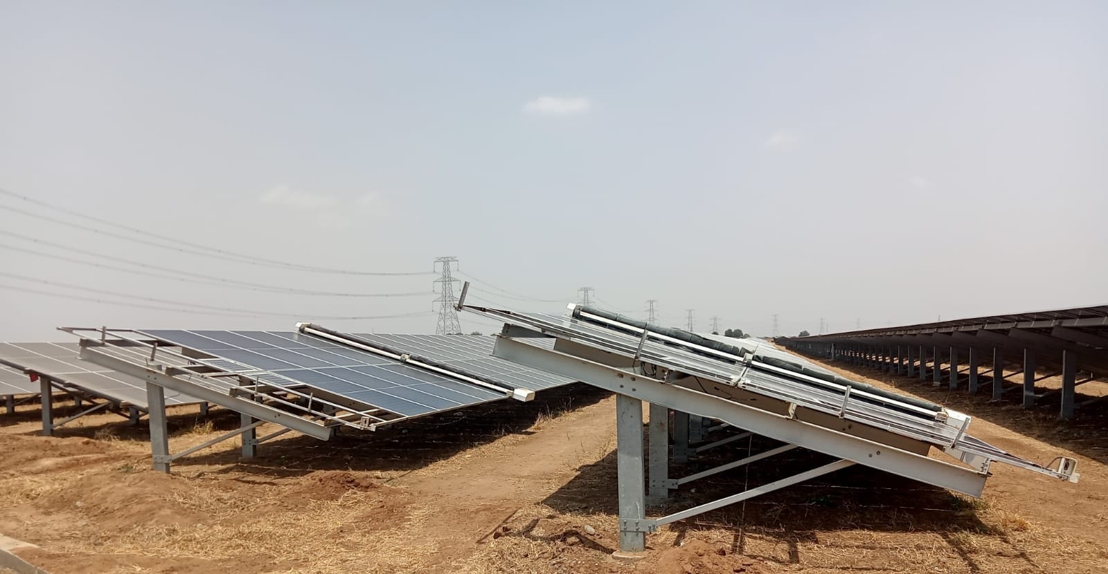
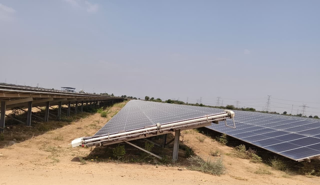
O&M teams see this as frequent disconnects during cleaning cycles. A robot that loses connection mid-row becomes a bottleneck, requiring manual retrieval, which is a huge risk for causing microcracks on modules. Since Wi-Fi signals struggle to pass through metal mounting structures, a mesh architecture is the fix. Each robot acts as a relay, extending your range without needing more central gear. It's self-healing, rerouting data if a node gets blocked. For 10MW or 50MW portfolios, mesh networking isn't optional; it's a requirement for managing robotic cleaning systems in regions like Rajasthan or Gujarat.
Technical implementation of wireless mesh networking for robot fleets
Deploying a mesh network takes a bit of planning. Start by placing industrial mesh nodes at least every tenth row, don't let intervals exceed 80 meters if you want strong signals in dusty conditions. Because mounting structures in Rajasthan or Gujarat block signals, use sub-GHz frequency hopping. It penetrates metal racking much better than standard Wi-Fi.
Your gateway should sit in the plant control room, using 4G/5G or fiber-optic links to bridge your robotic cleaning systems with the NECTYR interface. Every robot needs a dual-radio client to handle seamless handoffs as they move across 5MW or 50MW blocks. Aim for a signal-to-noise ratio of at least 25dB to prevent cleaning lag. This mesh setup allows for automated rerouting, supporting long-term O&M strategies without the headache of manual troubleshooting.
Advertisement
Hardware commissioning and signal validation
- Mesh Node Density: Place nodes every 50 to 80 meters to maintain a redundant, self-healing path.
- Frequency Selection: Use a hybrid approach. 2.4GHz for high-bandwidth telemetry and sub-GHz bands for critical control sequences.
- Latency Benchmarking: Run an on-site signal sweep. You must confirm end-to-end latency stays under 200ms for reliable real-time safety stops.
- Protocol Security: Use encrypted handshakes at the node level to keep fleet commands secure.
How to ensure mesh connectivity doesn't interfere with SCADA systems?
Frequency management is everything here to prevent signal degradation in your SCADA systems. Most sites already use 400MHz or 900MHz for SCADA, so use a frequency-hopping protocol to stay safe. Running your mesh on the 868MHz or 915MHz ISM bands keeps robot commands clear of grid traffic.
Physically separate your antennas. Keep mesh node antennas at least 1.5 meters away from SCADA gateways. If you're running sites over 50MW, use a Virtual Local Area Network (VLAN) to separate fleet data from SCADA packets. This ensures high-volume data from robotic cleaning systems doesn't slow down your inverter monitoring.
During setup, perform a spectrum analysis to identify existing RF noise. In Gujarat, where multiple blocks might share infrastructure, this is vital. Also, ensure your mesh gateway has a separate power supply from grid relays to prevent electromagnetic interference (EMI). These steps are essential for sites using predictive soiling modeling.
Optimal node placement and frequency selection for 5MW+ sites in India
At 5MW+ sites, node placement has to prioritize line-of-sight and avoid structural obstacles. For fixed-tilt setups, mount gateways at the highest available point, ideally near inverter skids or combiner boxes. If your rows exceed 100 meters, use repeater nodes every 50 to 60 meters, this is standard practice for Rajasthan or Gujarat.
Stability comes down to frequency choice. Standard 2.4GHz Wi-Fi is often unreliable in large plants because signals reflect off glass and face heavy interference. Use the Sub-GHz band (868MHz or 915MHz) for control signals; they penetrate dense rows and handle dust or humidity better. Save 5GHz for high-speed tasks like firmware updates at docking stations.
Watch out for signal collisions. Make sure your frequency doesn't overlap with weather sensors. For 50MW+ parks, do a signal survey first to map dead zones caused by electrical hum or metal housings. Use a redundant gateway setup for reliability, allowing for automated failover if a node loses power. This keeps your robotic cleaning cycles running smoothly.
Step-by-step: Deployment schedule for robot networking infrastructure
A phased rollout prevents network saturation and helps robotic cleaning systems integrate smoothly with your existing comms. Follow this schedule for 5MW to 10MW blocks in India:
- Week 1: Site RF Survey and Base Mapping. Use a spectrum analyzer to map signal density and find interference from inverters or SCADA gateways.
- Week 2: Gateway and Backbone Installation. Mount primary gateways at the substation using shielded cabling. Keep data lines 1.5 meters away from high-voltage lines.
- Week 3: Node-to-Robot Pilot Testing. Test 2 to 5 robots in a controlled row. Check signal handoff during a cleaning cycle; packet loss should stay below 2%.
- Week 4: Full Fleet Commissioning and Load Balancing. Scale the fleet across the plant. Assign robots to gateways by proximity and use VLAN partitioning for 50MW+ plants.
This sequence ensures data-heavy tasks don't tank performance. Updates or logs from automatic cleaning systems won't drag down the plant. I'd recommend checking the network every 90 days to account for any site changes in Rajasthan or Gujarat.
Implementation checklist for O&M engineers
Use this checklist when commissioning 5MW to 10MW plants:
- Spectrum Clearance: Set gateways to channels outside existing SCADA Wi-Fi to avoid packet loss.
- Node Redundancy: Install battery backups at every master gateway to help with recovery after power fluctuations.
- Signal Coverage Map: Check RSSI at every row end; keep values above -75 dBm.
- VLAN Isolation: Route robot traffic on a separate VLAN so diagnostic data doesn't slow the grid.
- Firmware Synchronization: Schedule updates during low-irradiance hours to preserve bandwidth during peak sun.
- Routine Connectivity Audit: Check signal intensity every 90 days to account for vegetation or site changes.
Following these protocols helps manage robotic cleaning systems on large sites. By monitoring packet rates and signal-to-noise ratios, you can catch faults early and prevent soiling losses. For teams using automatic cleaning, these safeguards are non-negotiable.
What plant managers should do next
- Conduct an RF Audit: Bring in a specialist for a site-wide spectrum survey to find interference from inverters or sensors.
- Specify Network Compatibility in RFPs: Require industrial RF protocol compatibility to ensure robots actually work on 5MW+ sites.
- Pilot in a Controlled Block: Start with a small section of the plant to verify how signals propagate through the rows.
- Integrate with Performance Monitoring: Make sure fleet software like NECTYR integrates with your site tools to help plan cleaning cycles.
Sources and further reading
Frequently asked questions
Solar robot fleets at the 5MW scale need wireless mesh networking. Move from a hub-and-spoke model to a self-healing mesh topology.
To prevent interference with existing SCADA or string-monitoring systems, you must maintain a minimum 20dB signal separation between the mesh network and existing plant frequencies.
A decentralized mesh architecture is essential for large-scale assets in India to maintain reliable communication across expansive and dusty sites where traditional star-topology Wi-Fi signals degrade rapidly.
Reliability is achieved by using sub-GHz bands, such as LoRa, for long-range command signals and 2.4GHz for high-bandwidth telemetry, while targeting end-to-end latency below 200ms for real-time command and control.