Quick answer
Designing for row spacing design cleaning robot compatibility requires specific clearance and geometry thresholds that go beyond standard land-use planning. For 5MW+ utility sites in India, ensuring your site layout supports automated equipment prevents manual intervention, reduces operating risk, and maximizes yield recovery across the lifecycle of the plant.
- Ensure a minimum inter-row clear width of 450mm to 600mm to accommodate standard robotic dimensions and maintenance movement.
- Limit terrain undulation to less than 5 degrees to maintain consistent brush-to-module contact pressure.
- Implement uniform row lengths of 80–120 meters for optimized battery cycle efficiency and docking predictability.
- Expect a 15–30% increase in yield recovery when robot-compatible design eliminates manual 'no-clean' dead zones often found in irregular site layouts.
By treating the robot as a permanent piece of infrastructure rather than a post-commissioning afterthought, EPC teams can avoid costly retrofits or manual labor dependencies that erode margins. Proper planning is essential for preventing downtime on sites where soiling losses can reach up to 30% during arid seasons. For a deeper look at how these constraints impact long-term financial health, you can read our guide on soiling revenue loss on Indian utility solar plants. Aligning your hardware choices with compatible row spacing is the first step toward achieving the 99% cleaning efficiency common in highly automated fleets.
How does row spacing design impact cleaning robot compatibility?
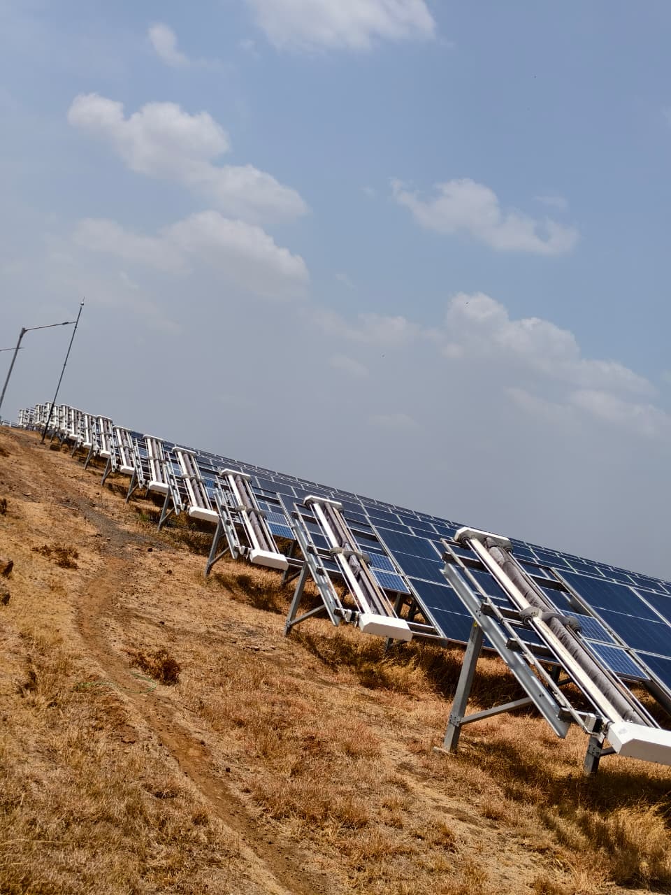
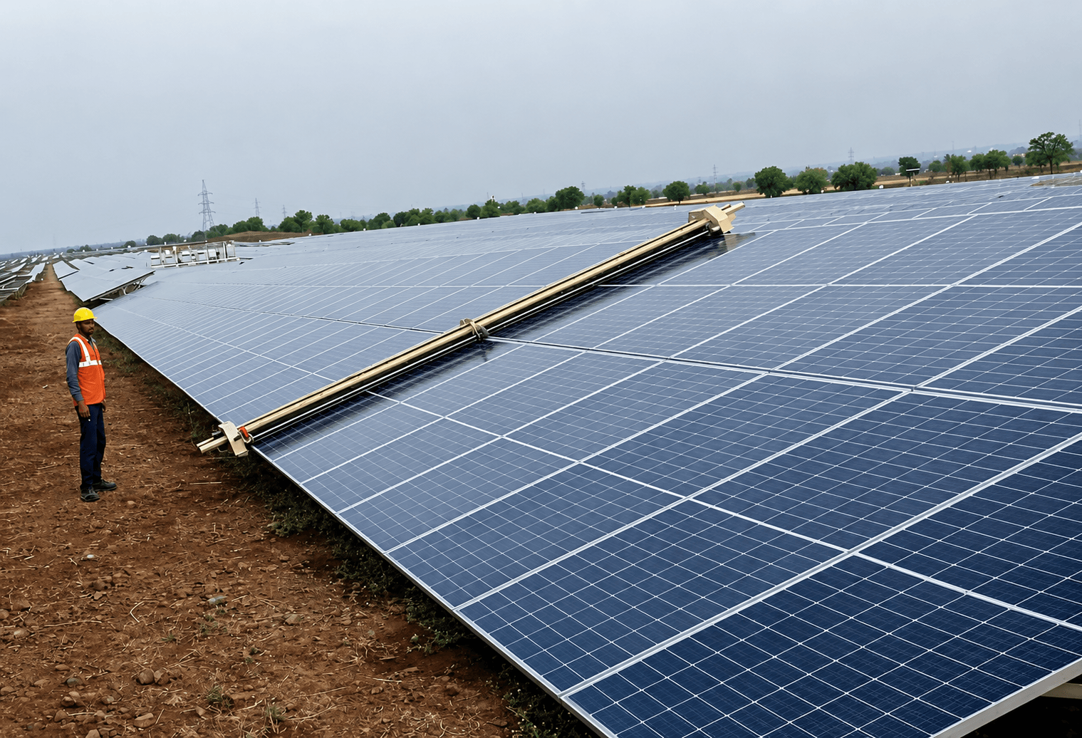
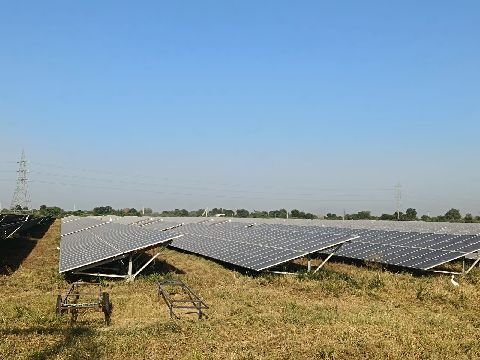
Row spacing dictates the physical freedom of your autonomous fleet. When utility-scale projects in India prioritize density to minimize land costs, they often create narrow inter-row corridors that block standard cleaning hardware. A constrained layout forces manual overrides or prevents robots from transitioning between rows, which effectively breaks your autonomous O&M strategy.
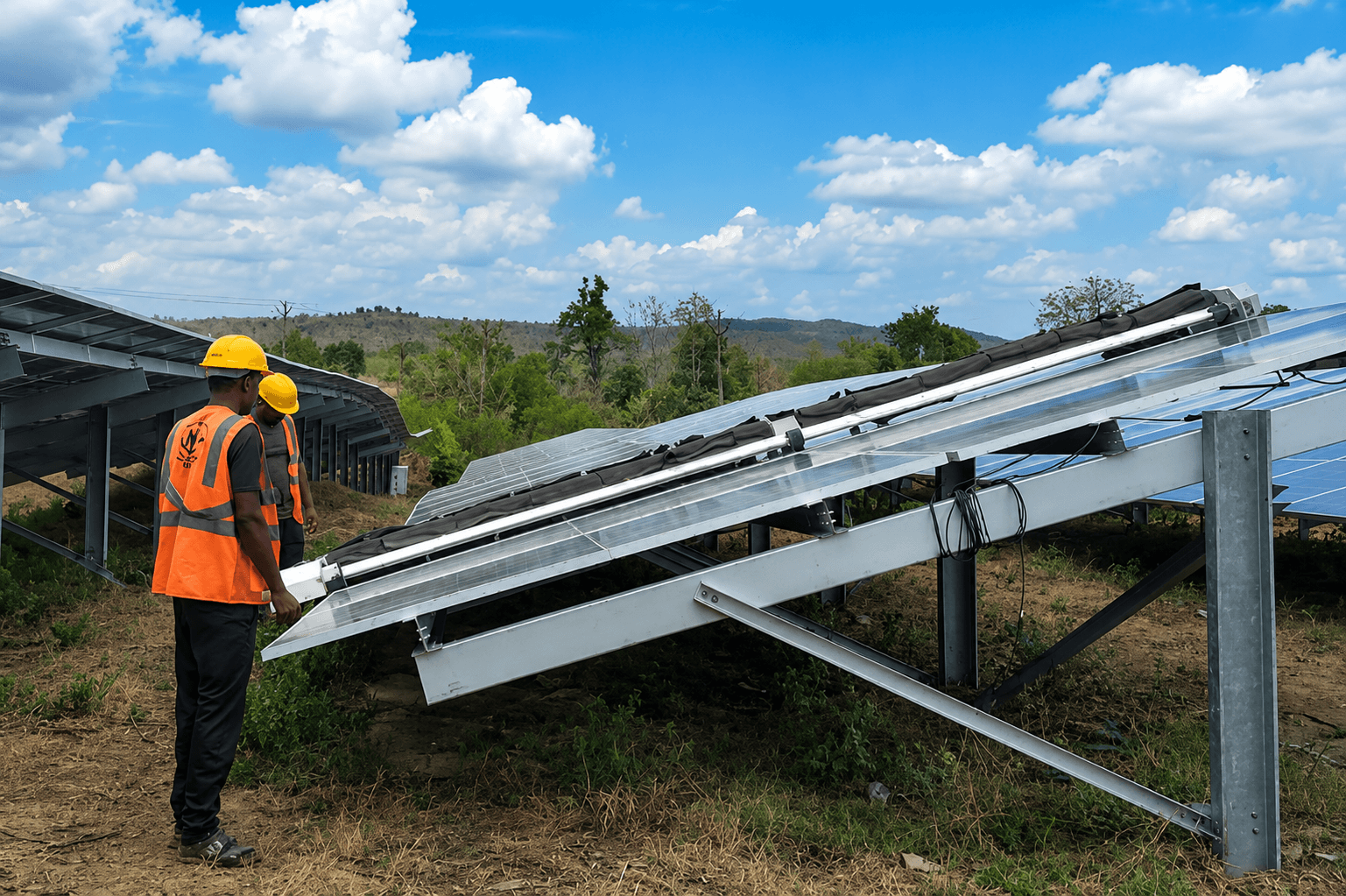
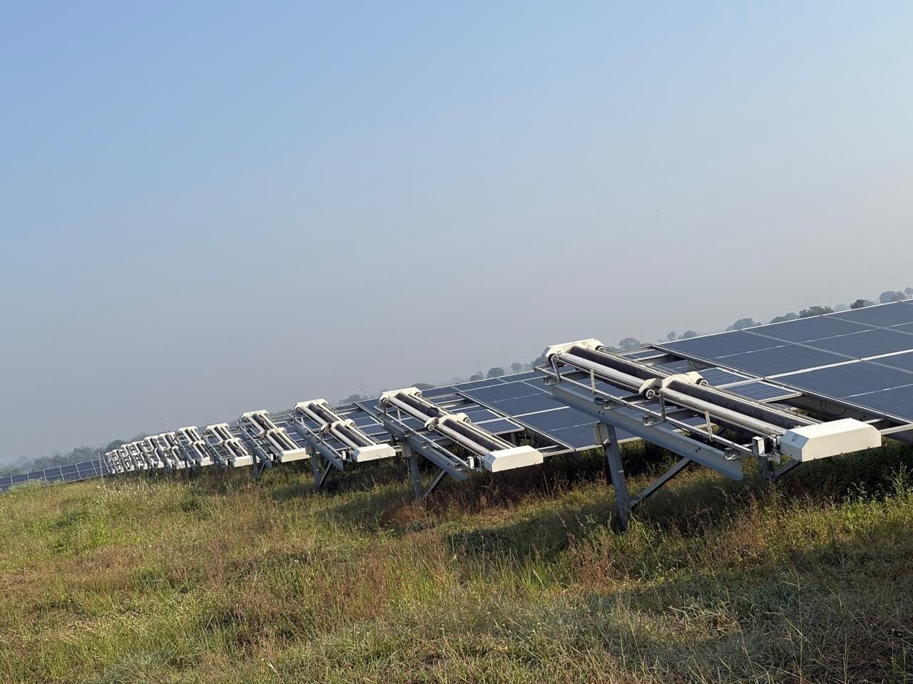
For tracker-mounted robots like the GLYDE-X or NYUMA-X, the spacing must accommodate not just the robot's footprint but the dynamic range of the tracker itself. When trackers reach maximum tilt (typically -52° to +52°), the trailing edge of the module row can obstruct the passage if the inter-row gap is insufficient. This physical interference forces downtime and limits the robot's ability to cover the array during peak soiling cycles, which in arid states like Rajasthan can trigger performance losses of up to 30% if cleaning is skipped.
Effective design requires a clear understanding of the robot's navigation geometry. You should analyze the following factors to ensure compatibility:
- Clearance at Full Tilt: Ensure the distance between the edge of a module row at full stow or tilt and the adjacent row allows for the robot's width plus a 50mm safety buffer.
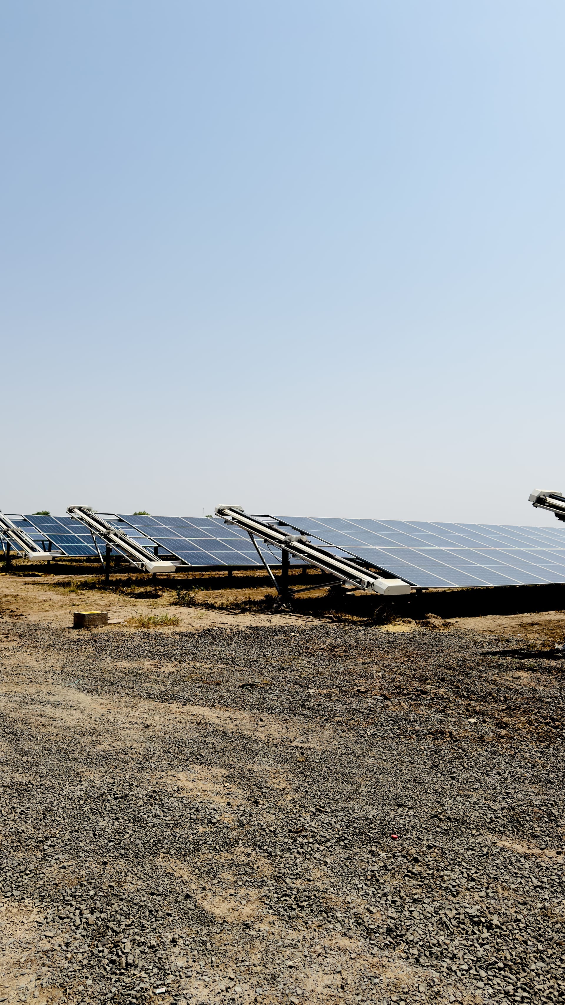
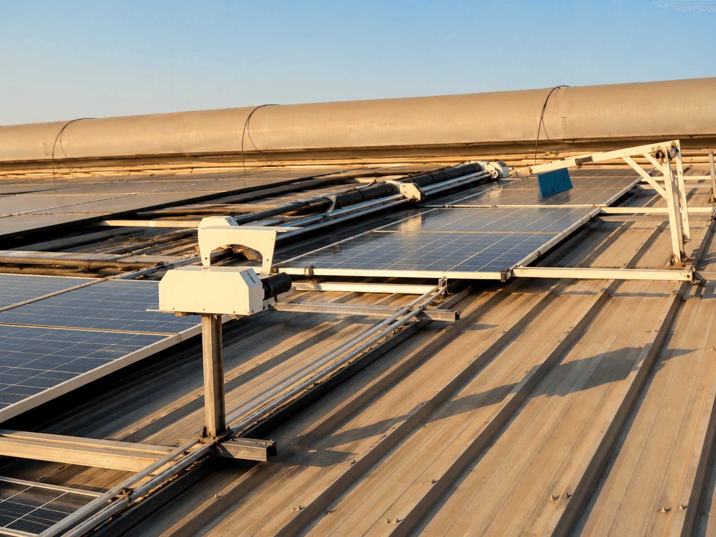
- End-Row Rail Integration: If you plan to use row-transfer platforms like CRADYL, you must dedicate at least 4 meters of linear space at the end of every row to host the docking and rail infrastructure.
- Obstacle Clearance: Vertical obstructions like junction boxes, support pillars, or cable trays must be recessed or positioned outside the primary travel path to prevent sensor faults.
- Ground Levelling: While robots handle moderate undulation, extreme terrain spikes or large stones create vibration and brush-contact inconsistencies, necessitating a uniform ground grade before deployment.
By mapping these variables during the EPC phase, you avoid the high cost of post-commissioning retrofits. A design that accounts for the robot as a permanent site asset ensures the machine can navigate the entire 5MW+ site without human intervention. This consistency is critical for maintaining a 99% cleaning efficiency, as discussed in our guide on how automated systems monitor plant health at scale. Proper row spacing does more than support navigation; it directly protects your PPA generation guarantees by ensuring regular, automated dust removal regardless of site size or complexity.
Technical parameters for tracker-mounted robots
Integrating robotic cleaning on single-axis tracker sites requires strict adherence to mechanical tolerances that go beyond standard site clearing. For hardware like the GLYDE-X or NYUMA-X, the primary design constraint is the dynamic motion range of the tracker. Because trackers must reach extreme angles for stow mode or back-tracking algorithms, the cleaning unit must maintain a stable connection regardless of the tilt. In India, utility-scale tracker rows often exceed 100 meters, meaning any deviation in mounting alignment can cause the robot to lose contact or trigger safety faults.
Technical site managers should prioritize the following parameters when vetting robots for tracker compatibility:
- Tilt Tolerance: The robot must be rated for the full operational range of your tracker, typically -52° to +52°. Ensure the bridge mechanism, such as the 360-degree rotation found on the GLYDE-X, supports these angles without exerting mechanical strain on the module surface.
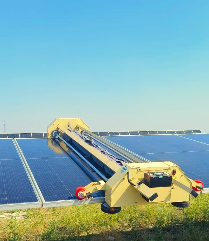
- Bridge Flexibility: Tracker rows are rarely perfectly linear over their entire length. A rigid body will experience high wear or derailment on even minor longitudinal undulations. Selecting a model with an articulated, flexible chassis allows the unit to maintain consistent brush-to-module contact throughout the full length of the tracker table.
- Row Transfer Mechanics: If you are deploying robots across multiple rows, consider the infrastructure needed for row-transfer units like the CRADYL. This platform requires a level, reinforced rail system at the end of the rows to enable automated docking. Without this, you are relegated to manual pick-and-place, which significantly increases labor overhead and increases the risk of panel edge damage.
- Weight and Pressure: Even on modern bifacial modules, the static load must not exceed the manufacturer-specified pressure limits, especially in extreme heat conditions where module temperature peaks. Most utility-grade robots are engineered for low-pressure contact to prevent micro-cracks, but confirming the robot's weight against the specific panel mounting hardware is a non-negotiable step for site commissioning.
These technical thresholds ensure your robotic fleet maintains its 99% cleaning efficiency without creating unforeseen maintenance tickets. For teams transitioning to this model, it is vital to reconcile these physical constraints with your existing site layout. If your current design lacks the clearance for these docking requirements, retrofitting should focus on creating end-row buffers rather than attempting to force units into tight, non-compliant spacings. You can review how these technical integrations affect long-term O&M budgets in our comparison of CAPEX versus OPEX cleaning models.
Overcoming site-specific layout constraints in India
Utility-scale projects in India often face land scarcity, leading to higher-density row spacing that complicates robotic deployment. When initial site plans fail to account for maintenance paths, the result is frequently high-cost manual retrofitting or reduced cleaning frequency. For plants in regions like Rajasthan or Gujarat, where dust accumulation can trigger 15% to 30% yield loss in dry seasons, row spacing design must include adequate end-row buffer zones to facilitate autonomous turning and charging.
Technical site managers should address these constraints by evaluating three critical layout factors:
- End-Row Clearance: Ensure at least 4 to 6 meters of leveled ground at the end of each row to allow robots to safely exit the table, dock, or navigate row-transfer units like the CRADYL. Constricted layouts often lead to collision risks and unnecessary equipment downtime.
- Slope and Terrain Grading: While robots are capable of managing minor undulations, steep gradients exceeding 15 degrees E-W or 18 degrees along the row-transfer path can cause navigation failures. Consistent grading during the EPC phase prevents the high cost of manual intervention on uneven terrain.
- Bifacial Shadowing and Proximity: Ensure that the robot's stow and maintenance positions do not create localized shade on modules. Precise row spacing design that respects the robot's physical dimensions ensures that maintenance never conflicts with the PPA generation target of the plant.
By conducting a pre-commissioning audit of row spacing design and cleaning robot compatibility, developers can avoid the common trap of retrofitting platforms at 50MW+ scale. Aligning your layout with the mechanical footprint of your selected robotic fleet is a critical, cost-effective step for any Indian IPP seeking to minimize long-term OPEX. We previously analyzed how these CAPEX versus OPEX models impact deployment strategy across large portfolios. For teams currently struggling with layout bottlenecks, focusing on end-row infrastructure and consistent site leveling provides the highest return on operational efficiency.
How can you prevent robot interference with site infrastructure?
Preventing operational friction requires proactive physical and digital site management. As robotic deployments scale across 5MW+ portfolios, the most frequent cause of downtime is not mechanical failure but physical interference with existing site infrastructure like cable trays, combiner boxes, and monitoring sensor arrays.
To mitigate these risks during the design or retrofitting phase, consider these infrastructure strategies:
- Cable Management Elevation: Ensure all string and home-run cables are firmly secured under the modules, clear of the robot path. On tracker systems, drooping cable loops can snag the robotic brushes or chassis, leading to expensive on-site repair visits.
- Sensor and Metering Buffers: Secondary hardware, such as pyranometers or soiling stations, must be positioned at least 1 meter away from the robot travel zone. If this is impossible, install physical protective barriers that allow the robot to pass safely without making physical contact with sensitive electrical components.
- Junction Box Clearance: In high-density row designs, combiner boxes often sit near the end-of-row turning area. Shift these units to lateral positions or elevated stands to ensure the robot can maneuver for charging or row transfer without structural collision risks.
- Digital Geofencing: Use the robot's navigation software to implement virtual exclusion zones. For assets integrated with fleet platforms like NECTYR, mapping out obstacles in the digital twin allows the robot to identify and avoid fixed site obstructions before it reaches them.
By treating robotic compatibility as a core component of the site layout rather than an afterthought, operators significantly reduce the need for manual site interventions. Poorly placed infrastructure is a leading cause of downtime, which directly impacts your overall soiling revenue loss calculations. For large-scale projects, it is also beneficial to review the impact of CAPEX versus OPEX cleaning models on how your site infrastructure is maintained by third-party O&M teams. Addressing these physical clashes early during the plant commissioning phase prevents costly site modification work later in the asset lifecycle.
Checklist for pre-commissioning robot-ready sites
For utility-scale projects ranging from 5 MW to 500 MW, verifying robot compatibility during the EPC phase is far more cost-effective than attempting field retrofits. Follow this operational checklist to ensure your plant layout supports autonomous navigation from day one:
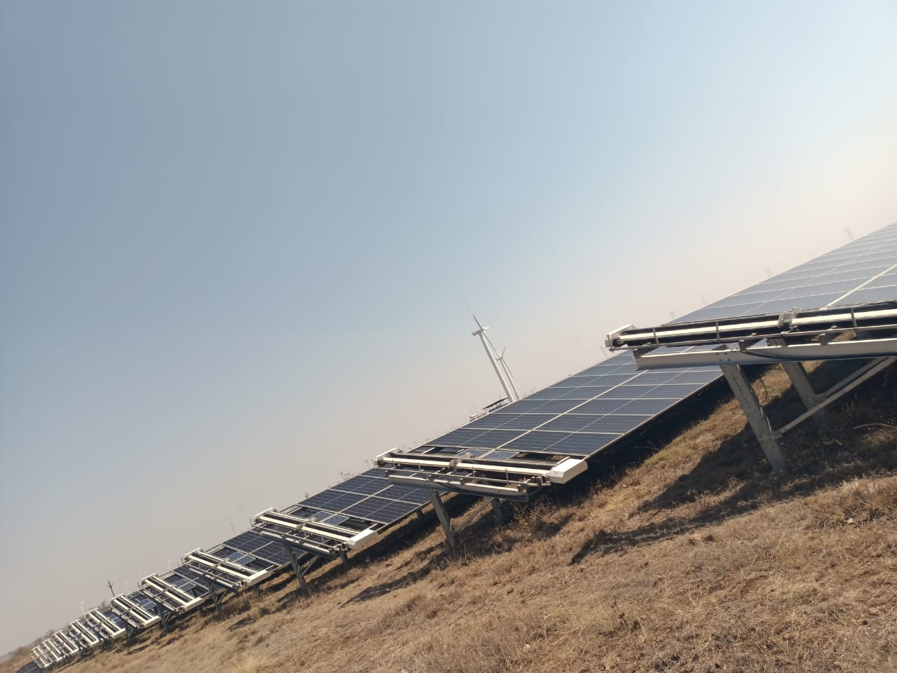
- Row Length Uniformity: Standardize row lengths where possible. Ensure end-row clearance of at least 3 to 4 meters to allow for robot docking, battery swapping, or movement via specialized transfer platforms like the CRADYL.
- Cable Management Routing: Secure all DC string cables and home-run wires within cable trays or conduits. Protruding loops or sagging wires are primary trip hazards for robotic brushes and can lead to structural damage.
- Slope and Leveling Audit: Confirm that the E-W and N-S slopes do not exceed the mechanical limits of your selected fleet. Most utility robots, including the NYUMA or GLYDE series, are optimized for terrains under 15-degree inclines.
- Structural Obstacle Clearance: Perform a physical sweep for potential collision points. This includes ensuring that combiner boxes, weather stations, and tracker drive motors are offset from the primary path of the robot.
- NECTYR Digital Twin Integration: Import your site CAD layout into your fleet management software before commissioning. Mapping exclusion zones, such as sensitive instrumentation or perimeter fencing, prevents unintended collisions during autonomous operation.
- Surface Continuity: Ensure that tracker-to-tracker bridge gaps are within the tolerance levels of your robotics provider. For trackers, confirm the mechanical articulation range is cleared of any site-installed hardware that might snag a 360-degree bridge.
These layout refinements reduce downtime, which is essential given that dust-related losses in semi-arid regions like Rajasthan can fluctuate between 15% and 30% without consistent cleaning. By synchronizing your plant design with your O&M robotics strategy, you ensure that the revenue leakage caused by soiling is minimized during the critical first year of operation.
Key takeaways for plant managers
- Plan for Automation Early: Treat robotic compatibility as a non-negotiable EPC requirement to avoid high-cost site modification fees post-commissioning.
- Standardize Site Layouts: Consistency in row length and end-of-row infrastructure directly improves fleet reliability and simplifies the scheduling logic in NECTYR.
- Monitor Infrastructure Interference: Proactively clear cables and sensors from the robot travel zone to prevent mechanical failures that drive up OPEX.
- Focus on Lifecycle ROI: Integrating waterless robotic cleaning technology, which can reduce water use by up to 90% compared to wet cleaning, requires a site design that facilitates autonomous, rather than manual, movement.
Sources and further reading
Frequently asked questions
Designing for row spacing design cleaning robot compatibility requires specific clearance and geometry thresholds that go beyond standard land-use planning. For 5MW+ utility sites in India, ensuring your site layout supports automated equipment prevents manual intervention, reduces operating risk, and maximizes yield recovery across the lifecycle of the plant.
You must account for both the physical footprint of the robot and the dynamic tilt range of the trackers. Because trackers often tilt up to 52 degrees in either direction, the inter-row gap must be wide enough to prevent the trailing edge of the module row from obstructing the robot during full-tilt operations.
Yes. Optimizing row spacing allows autonomous fleets to eliminate manual no-clean dead zones, which often results in a 15-30 percent increase in yield recovery. In arid regions where soiling losses can reach 30 percent, this layout optimization is critical for maintaining high performance ratios.
Retrofitting legacy sites is possible but often costly and complex. Because standard cleaning hardware requires specific spacing and geometric thresholds, EPC teams should treat robots as permanent infrastructure during the initial design phase to avoid the significant operational friction and labor dependencies associated with irregular or cramped site layouts.